JC-4s Automatic Antenna Tuner model 2023
1KW DUAL MEMORY AUTO ANTENNA COUPLER
Highlights :
- 1Kwatt PEP (SSB) max power for 25 meter long antennas (1,6 – 30 Mhz)
- 50 memories in each antenna output (“A” and “B”)
- Antenna switching between A and B without retuning
- “tuned” start up at the last used frequency
- Memory storage without internal batteries
- Possible to connect with command from most Icom, Kenwood & Alinco transceivers
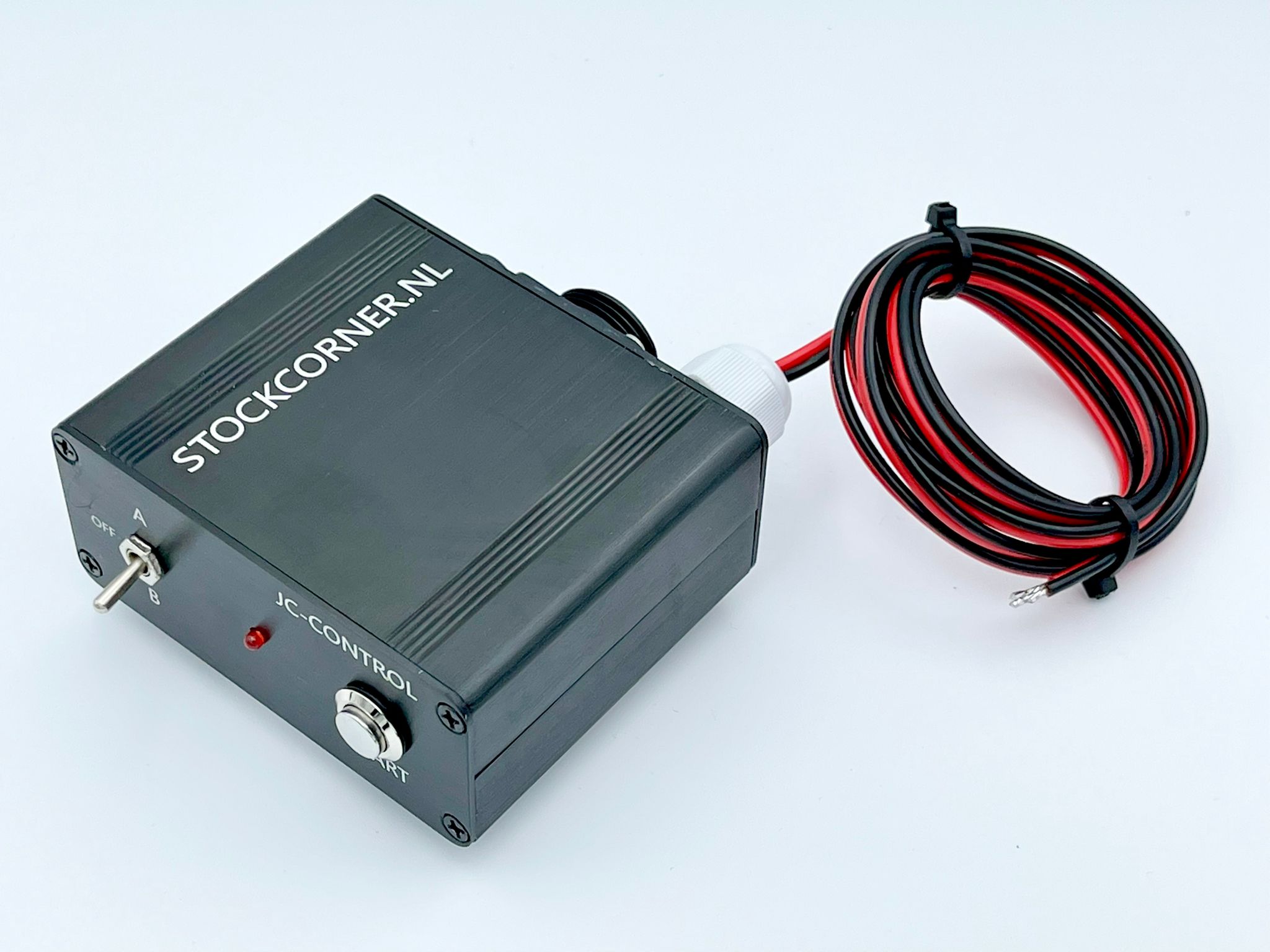
- Possible to connect with any HF radio with the provided control box
- 6pF output capacitor steps
- Possible to connect a dipole direct to “A” & “B”
- Grounding of the not used antenna output while operating the other
- Grounding of both antenna outputs if the 12v DC supply is cut
- Improved design of the capacitor board (version S)
- Improved input SWR during the tuning process (version S)
- Improved security : When too much RF power during tuning process, Tuning will be interrupted (version S)
- New design control box (included with order)
- If needed a "N" connector can be mounted in stead of PL-259 on request
ALL OUR PRODUCTS ARE HANDMADE. NO AUTOMATIC PRODUCTION LINES !!
Please download the complete manual version 9 from this website. This will give you many answers to your questions.
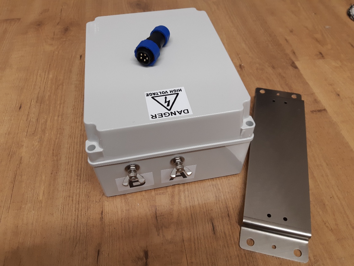
What will you get if you order: JC-4s, Control Box, 2 x 5 pin connector, mounting Innox iron, manual and good packing.
Heredown you see the total box which is UV protected against sunlight
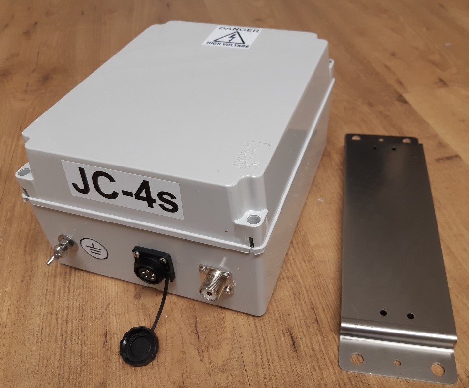
|
Circuit type |
ReversibleLorΠ |
|
Input capacitance step |
25pF |
|
Output capacitance step |
6pF |
|
Inductance step |
0.08μΗ |
|
Total capacitance |
3400pF |
|
Total inductance |
80μΗ |
|
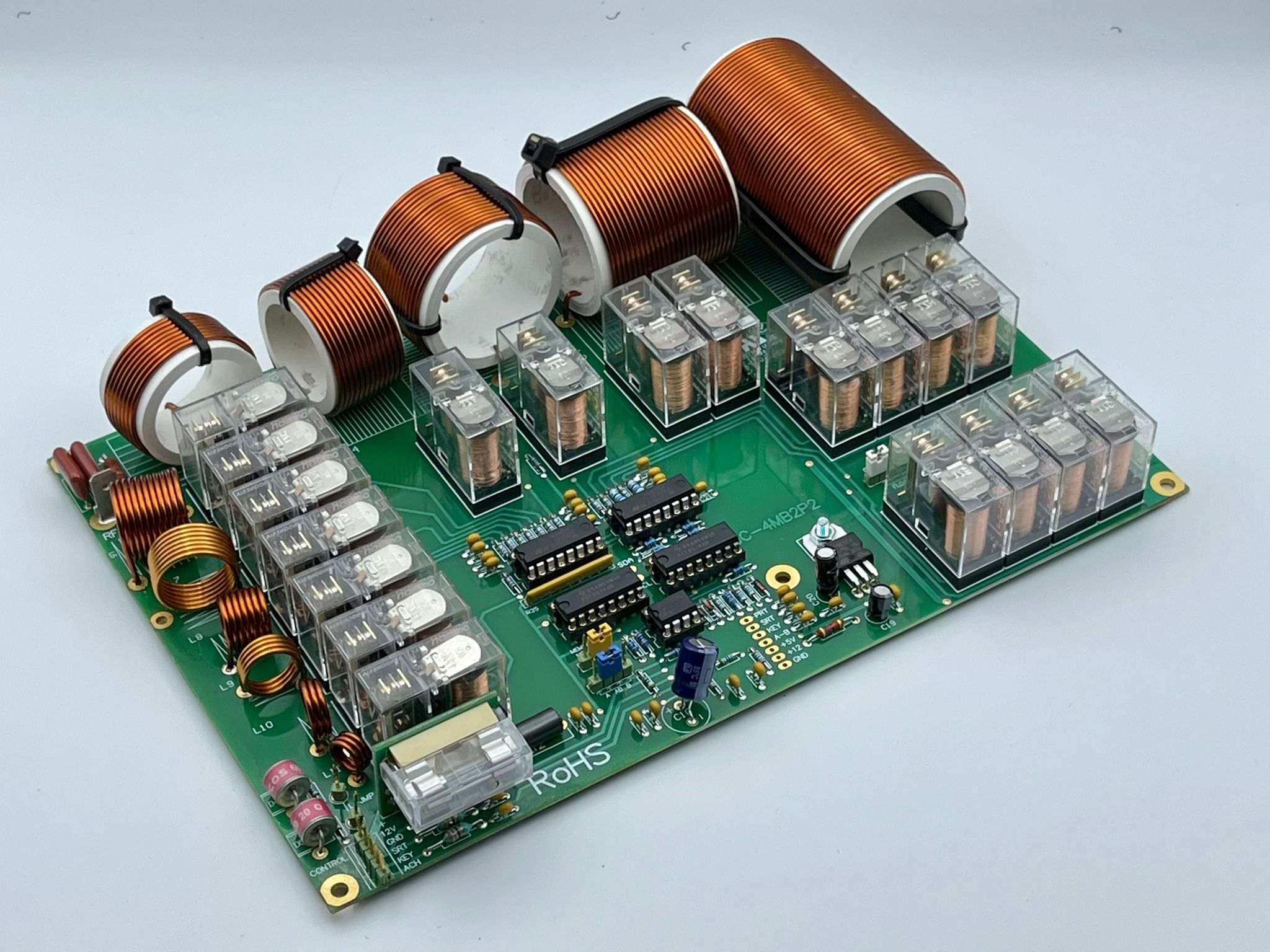
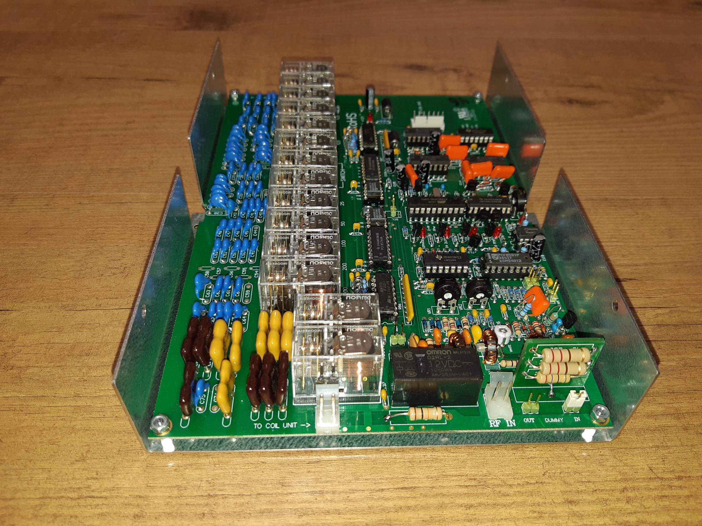
UsedRELAYS |
32 X OMRON |
|
Operating frequencies |
1.6 to 30 ΜΗΖ |
|
Maximum power for 25 meters antenna |
1000W SSB ( 300W on AM, FM, CW, RTTY & all other carrier modes FOR A SHORT TIME!!! ) |
|
ATMEL controller |
ΑΤ89C4051 - 24P |
|
Communication with RELAYS and memories |
I2C |
|
Maximum tuning power |
50 W (carrier) |
|
Typical tuning time |
2 – 3 sec. |
|
Maximum tuning time Memory tune time |
6 sec. 0.02 sec |
|
D.C. supply voltage |
11 – 16 V |
|
Maximum supply current |
1.2A |
|
Typical VSWR ( in the tuner input ) |
< 1.2 : 1 |
|
Maximum VSWR (in the tuner input) |
< 1.6 : 1 |
|
Protection |
Static discharge (NOT FOR THUNDER FALL!) |
|
Dimensions ( without metal holder ) Weight
|
19.5 x 25 x 13.5 cm 2.5 Kg
|
TUNING PROCEDURE USING THE STANDARD CONTROL BOX
- We set the jumper switch of the control box to antenna "Α" or "Β".
- We set the transceiver in FM, RTTY or CW mode and we adjust the output carrier power
somewhere in between 10 and 20 watts.
- We push the button on the control box until the red LED is lit
- We activate PTT keeping the transceiver transmitting some power.
- We wait until the LED goes off and then we stop transmitting. During this process you can hear
all relays fast clicking if you are nearby the coupler. If the LED goes off the “tune process” is finished.
(The SWR must be 1:1) If you push the tune button of the control box and if you do NOT activate your transmitter the led will go off after a few seconds.(time out)
If the LED quickly turns on and off at the end of the tuning procedure, the tuning procedure has failed!
We set the switch of the control box to antenna "Α" or "Β". We set the transceiver in AM,
FM , RTTY or CW mode and we adjust the output carrier power somewhere in between 10
and 20 watts. We activate PTT keeping the transceiver transmitting. We push the button on
the control box until the red LED is lit. We wait until the LED goes off and then we stop transmitting.
With this same control box you can erase the memories if wanted. The design inside is very
simple so you can reproduce it easily to your own demands and quality.
CONNECTION TO NEW IC-7300 :